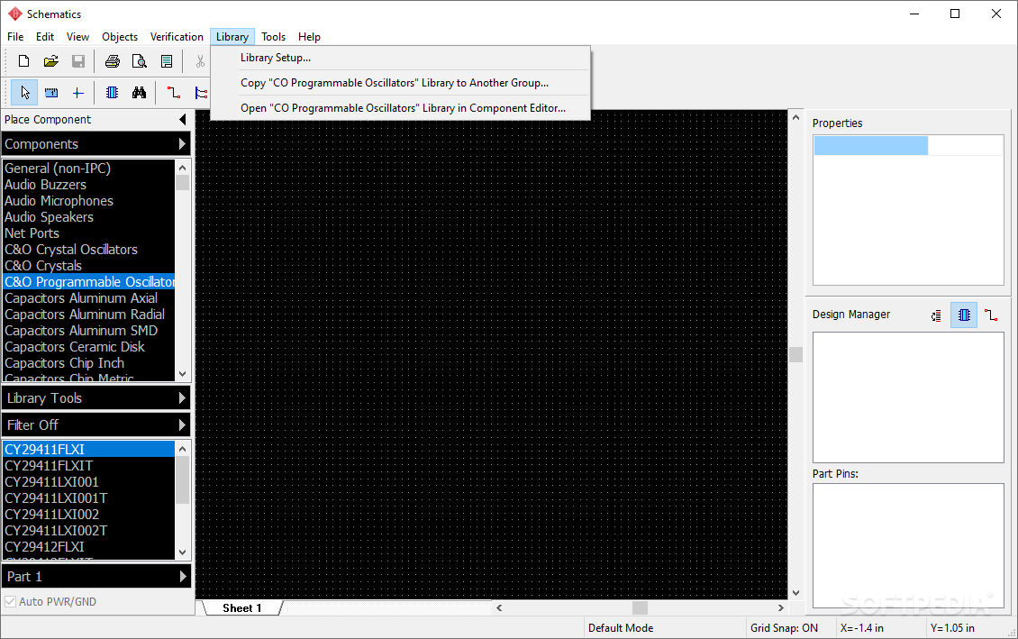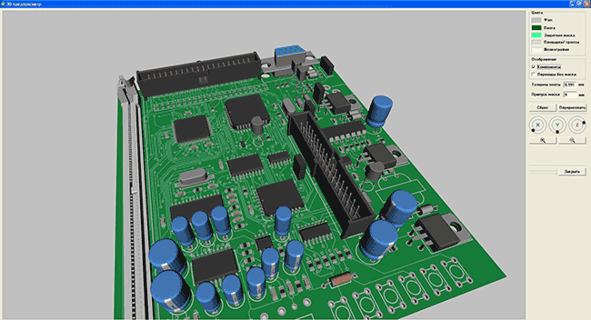


As soon as the ultrasonic waves received by the receiver circuit after striking with an object, the echo pin goes low.These waves travel through the air and if there is any object placed in parallel to the sensor, these waves reflect back after a collision with the object.When the Echo pin goes high, We start to measure time with the ESP32 duration measurement function.At the same time, the Echo pin also makes a transition from a logic low level to a logic high level. As soon as 10µs input trigger signal becomes active low, the transmitter circuit produces a burst of 8 ultrasonic sonar pulses.To start ranging with HC-SR04, first, we apply 10µs pulse to the trigger pin of the HC-SR04 sensor from the ESP32 digital output pin.The functionality of this software is rather complex as this is a professional design tool. Please be aware that this article is going to be extremely coarse as it is supposed to be a general overview of the DipTrace software. This mini project was perfect for my first steps with DipTrace. I needed a super small PCB for 78XX type voltage regulators.

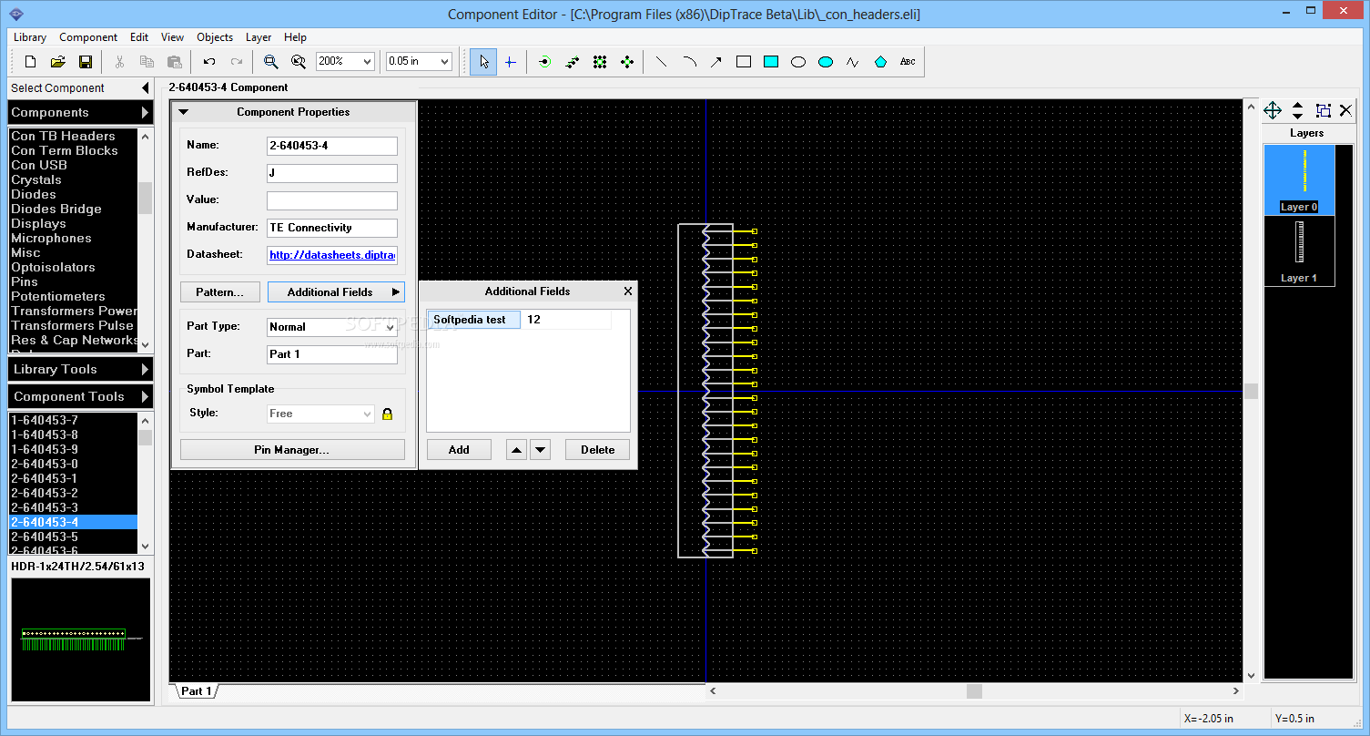
In case a part or footprint is not included in the libraries, DipTrace offers both a component editor and a pattern editor for custom parts. All versions of DipTrace come with a humongous parts library and 3D models for a large amount of general purpose parts. DipTrace Full offers unlimited pins and unlimited signal layers for $ 895. The cheapest version, DipTrace Starter (300 pins, 2 signal layers), is available for $ 75. Since I needed a super simple PCB for some 78XX / 79XX type linear regulators, I decided to use this opportunity for my first steps with DipTrace.ĭipTrace offers different prices for different packages. I had it installed on my computer for over a year but have never really used it.

Huge List of tutorials & Components based resources.


 0 kommentar(er)
